
Understanding solid state relay (SSR) diagrams is a cornerstone of safe and efficient electrical system design. Awareness of these diagrams empowers engineers, technicians, and industrial personnel to perform precise installations and maintain reliable operations. By focusing on proper configuration practices, industries can minimize downtime and optimize system performance.
The Importance of SSR Diagram Awareness
- Enhanced Safety: Clear understanding of SSR diagrams ensures connections are accurate, reducing the risk of short circuits, overloads, and equipment damage.
- Efficient Troubleshooting: Technicians can quickly identify potential issues, such as incorrect wiring or faulty input/output connections, leading to faster maintenance.
- Optimized System Performance: Proper configuration guided by diagrams maximizes the lifespan of SSRs and connected devices, improving operational efficiency.
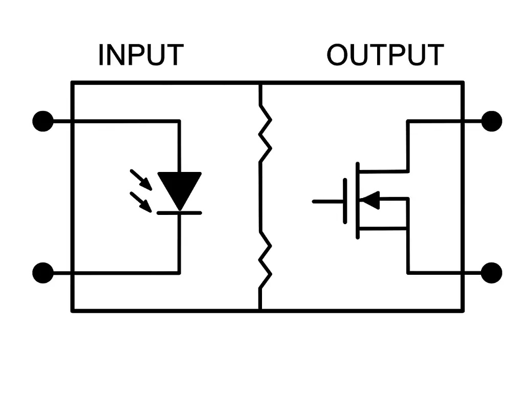
Key Elements in a Solid State Relay Diagram
- Input Control Terminals: Diagrams highlight input terminals that accept low-voltage signals to control high-power loads safely.
- Load Output Connections: Proper identification of load terminals ensures the relay switches the correct devices without overloading circuits.
- Opto-isolation Indicators: SSR diagrams show opto-isolated sections that separate control circuits from high-voltage outputs, enhancing system safety.
- Control Voltage Ratings: Awareness of voltage levels specified in diagrams prevents accidental mismatches and potential relay failure.
Best Practices for Installation Using SSR Diagrams
- Follow Diagram Instructions Meticulously: Adhering strictly to diagram specifications ensures every connection supports the intended load and control logic.
- Verify Input and Output Ratings: Double-checking voltage and current ratings reduces risks of overloading and system malfunctions.
- Use Correct Wiring Techniques: Proper wire gauge selection and secure terminal connections prevent overheating and energy loss.
- Test Configurations Before Operation: Performing pre-operation checks according to the diagram enhances confidence in system reliability.
Benefits of Proper SSR Configuration
- Reduced Downtime: Correct installations guided by diagrams prevent unnecessary system interruptions.
- Increased Reliability: Consistent adherence to diagram instructions ensures long-term stability in high-demand industrial environments.
- Simplified Maintenance: Clear documentation through SSR diagrams makes it easier for new personnel to understand system layouts and perform updates safely.
- Energy Efficiency: Properly configured SSRs minimize unnecessary power dissipation, contributing to sustainable operations.
Building Confidence Through Diagram Awareness
Developing SSR diagram literacy transforms the approach to industrial electrical systems. Personnel equipped with this knowledge can execute installations with precision, troubleshoot effectively, and maintain equipment at peak performance. Organizations benefit from increased operational reliability, reduced maintenance costs, and safer work environments. A proper solid state relay diagram improves performance analysis.
Conclusion
Awareness and understanding of solid state relay diagrams are more than technical skills they are essential tools for ensuring proper installation, configuration, and operational safety. By integrating these practices into daily industrial routines, teams can achieve optimal system performance and long-term efficiency, fostering a proactive and confident approach to modern automation.